DESIGN OF VAPOUR ABSORPTION REFRIGERATION SYSTEM WORKING ON SOLAR HEAT GENERATOR
ABSTRACT
Most of the
energies are utilized by the industries due to depletion of fossil fuels and
increasing the fuel price and pollution. So that to overcome this problem we
have to use renewable energy source or utilize heat waste from different
company.Over the
past few decades, energy is the backbone of technology and economic
development. In addition to men, machines and money,‘energy’ is now the fourth
factor of production.The
objective of this UDP is to design and study an environment friendly vapour
absorption refrigeration system of 0.1 TON capacity using R 717 (NH3) and water
as the working fluids. So we have to use SOLAR HEATER in vapour absorption
refrigeration system in place of electrical heat generator.
Introduction
In physics, energy is a property of objects which can be
transferred to other objects or converted into different forms. The
"ability of a system to perform work" is a common description of
energy is measured in joules Common energy forms include the kinetic energy of
a moving object, the potential energy stored by an object's position in a force
field the elastic energy stored by stretching solid objects, the chemical
energy released when a fuel burns, the radiant energy carried by light, and the
thermal energy due to an object's temperature. All of the many forms of energy
are convertible to other kinds of energy. In Newtonian physics, there is a
universal law of conservation of energy which says that energy can be neither
created nor be destroyed; however, it can change from one form to another.
There are mostly we can classify energy in two according to
it’s renew rate in finite time
- Nonrenewable
energy
- renewable
energy
Nonrenewable energy
In layers of a non-renewable resource (also called a finite
resource) is a resource that does not renew itself at a sufficient rate for
sustainable economic extraction in meaningful human time-frames. An example is
carbon-based, organically-derived fuel. The original organic material, with the
aid of heat and pressure, becomes a fuel such as oil or gas.A mineral is a naturally occurring chemical compound. Most
often, they are crystalline and a biogenic in origin.A metal is a material (an element, compound, or alloy) that
is typically hard, opaque, shiny, and has good electrical and thermal
conductivity. Metals are generally malleable — that is, they can be hammered or
pressed permanently out of shape without breaking or cracking — as well as
fusible (able to be fused or melted) and ductile (able to be drawn out into a
thin wire). About 91 of the 118 elements in the periodic table are metals, the
others are nonmetals or metalloids. Some elements appear in both metallic and
non-metallic forms.Fossil fuels are fuels formed by natural processes such as
anaerobic decomposition of buried dead organisms, containing energy originating
in ancient photosynthesis. Coal is a combustible black or brownish-black
sedimentary rock usually occurring in rock strata veins called coal beds or
coal seams. The harder forms, such as anthracite coal, can be regarded as
metamorphic rock because of later exposure to elevated temperature and
pressure. Coal is composed primarily of carbon along with variable quantities
of other elements, chiefly hydrogen, sulfur, oxygen, and nitrogen.Petroleum is a naturally occurring, yellow-to-black liquid
found in geological formations beneath the Earth's surface, which is commonly
refined into various types of fuels. Components of petroleum are separated
using a technique called fractional distillation.Natural gas is a naturally occurring
hydrocarbon gas mixture consisting primarily of methane, but commonly including
varying amounts of other higher alkanes, and sometimes a small percentage of
carbon dioxide, nitrogen, hydrogen sulfide, or helium.Natural gas is a fossil fuel used as a source of
energy for heating, cooking, and electricity generation. It is also used as
fuel for vehicles and as a chemical feedstock in the manufacture of plastics
and other commercially important organic chemicals. It is a non-renewable
resource
Disadvantages of Non-Renewable Energy
• The
disadvantages to non-renewable energy indicates that once sources of
nonrenewable energies are gone they can't be replaced or revitalized.
• The
mining of non-renewable energy and the by-products they leave behind cause’s
damage to the environment. There is little doubt that fossil fuels contribute
to global warming. When fossil fuels are burned, nitrous oxides causes’
photochemical pollution, Sulphur dioxide creates acid rain, and greenhouse
gases are emitted.
• The
major disadvantage of nonrenewable energy is global warming. Which increase the
average temperature of earth that’s why the glaciers are continuously melting
and level of sea rise.
RENEWABLE ENERGY
Renewable energy is classified as energy that comes
from resources like sun light (known as solar), wind, and geo thermal heat and
rain that are constantly replenished. Renewable energy can serve as a
replacement to electricity, motor fuels, rural energy and heating. Many people
might discount renewable energy sources right off the bat just by looking at
the definition. They wouldn’t hesitate to question why it is necessary to
switch to sources like sunlight, wind, or rain. The way they see it, these are
not very reliable sources of energy.
Advantage of renewable energy
• Renewable energy is, well, renewable:
This means it has infinity of sustainability and we will never run out of it.
Other sources of energy like coal, oil and gas are
limited and will run out some day. Renewable energy can reduce our dependence
on fuels and energy from foreign governments. Strong winds, heat within earth,
moving water, shining sun can provide a vast and constant energy resource
supply.
• Environmental Benefits:
It is clean and
results in little to no greenhouse and net carbon emissions. It will not
deplete our natural resources and have minimal, if any, negative impacts on the
environment, with no waste products of Co2
and other, more toxic take with different sources of energy. The environmental
benefits of renewable energy are innovative in that they will dramatically
scale back on the amount of toxic air
pollution released
into the atmosphere by other methods. Enables us to protect the environment
from toxic pollutions, which in turn keep people healthier.
• Reliable Energy Source:
Our dependence
on fossil
fuels has
increased considerably in last few decades. The result is that our national
security continues to be threatened by our dependence on fossil fuels which are
vulnerable to political instabilities, trade disputes, wars, and high prices.
This impacts more than just our national energy policy. Also, solar and wind
plants are distributed over large geographical area and weather disruptions in
one area won’t cut off power to an entire region.
• Economic Benefits:
Renewable energy is
also cheaper and more economically sound than other sources of generated
energy. It is estimated that as a result of renewable energy manufacturing,
hundreds of thousands of stable jobs will be created. Thousands of jobs have
already been created in numerous European countries like the United Kingdom and
Germany, who have adopted measures to manufacture renewable energy. Renewable
energy amenities require a less amount of maintenance, which reduces the costs.
Switching to renewable energy sources also means that the future of our energy
is returned back to the people: to communities, families, farmers, and
individuals.
• Stabilize Energy Prices:
Switching to
renewable energy sources also means steady pricing on energy. Since the cost of
renewable energy is dependent on the invested money and not the increasing or
decreasing or inflated cost of the natural resource,
governments would only pay a small amount in comparison to the needlessly heavy
pricing of the energy prices we are witnessing currently.
DISADVANTAGE OF RENEWABLE ENERGY
• Reliability of Supply:
One
shortcoming is that renewable energy relies heavily upon the weather for
sources of supply: rain, wind, and
sunshine. In the event of weather that doesn’t produce these kinds of climate
conditions renewable energy sources lack the capacity to make energy. Since it
may be difficult to generate the necessary energy due to the unpredictable
weather patterns, we may need to reduce the amount of energy we use.
• Difficult to Generate in Large Quantity:
Another
disadvantage of renewable energy is that it is difficult to generate large
amount of energy as those produced by coal powered plants. This means that
either we need to set up more such facilities to match up with the growing
demand or look out for ways to reduce our energy consumption.
• Large Capital Cost:
Initial investments are
quite high in case of building renewable energy plants. These plants require
upfront investments to build, have high maintenance expenses and require
careful planning and implementation.
• Large Tracts of Land Required:
To meet up
with the large quantities of electricity produced by fossil fuels, large
amount of solar panels and wind farms need to be set up. For this, large tracts
of land is required to produce energy quantities competitive with fossil fuel
burning. Becoming more conscious about saving of energy for better future, we
can use wastage energy from industries like thermal energy from boiler exhaust
gases which can be utilize for heating of water, heating of ammonia water
solution in vapour absorption refrigeration system, for cooking purpose we can
use that steam for many other purpose so, by this way we can save the energy.
Since last few decades many countries were taken steps to reduce the global
warming which is very tough question rise against to all. We all now the
reasons behind the global warming which are mostly the more use of petroleum
product for getting power in daily life like electricity and more. The burning
of petroleum based product produce the gases which are harmful to ozone layer
around the earth and due to which the average temperature of earth increasing
continuously. Due to which glaciers are melting and sea level increasing so we
have to use that form of energy which is renewable as well as eco-friendly like
solar energy, wind energy, geo thermal energy, tidal energy, biomass,
hydropower wave power, bio fuel, etc.
TYPES OF RENEWABLE ENERGY
• Solar energy:
It is the energy which is
coming from sun in the form of electromagnetic waves. It contains no of
different wavelengths. The energy which reach to earth is depends on intensity
of radiation which is defined as energy focus on per unit area when area is
perpendicular to the radiation. The temperature of surface of sun is 6000 K. the intensity of
radiation on the earth is 1367 W/m2.
• Wind energy:
Wind power is the use of
air flow through wind turbines to mechanically power generators for
electricity. Wind power, as an alternative to burning fossil fuels, is
plentiful, renewable, widely distributed, clean, produces no greenhouse gas
emissions during operation, consumes no water, and uses little land. The net
effects on the environment are far less problematic than those of nonrenewable
power sources.
• Geo-thermal energy:
Earth's internal
heat is thermal energy generated from radioactive decay and continual heat loss
from Earth's formation. Temperatures at the core–mantle boundary may reach over
4000 °C (7,200 °F). The high temperature and pressure in Earth's interior cause
some rock to melt and solid mantle to behave plastically, resulting in portions
of mantle convecting upward since it is lighter than the surrounding rock. Rock
and water is heated in the crust, sometimes up to 370 °C (700 °F) Geothermal
power is cost-effective, reliable, sustainable, and environmentally friendly,
but has historically been limited to areas near tectonic plate boundaries.
• Bio fuel energy:
A biofuel is a fuel
that is produced through contemporary biological processes, such as agriculture
and anaerobic digestion, rather than a fuel produced by geological processes
such as those involved in the formation of fossil fuels, such as coal and
petroleum, from prehistoric biological matter. Biofuels can be derived directly
from plants, or indirectly from agricultural, commercial, domestic, and/or
industrial wastes. Renewable biofuels generally involve contemporary carbon
fixation, such as those that occur in plants or microalgae through the process
of photosynthesis. Other renewable biofuels are made through the use or
conversion of biomass (referring to recently living organisms, most often
referring to plants or plant-derived materials). This biomass can be converted
to convenient energy-containing substances in three different ways: thermal
conversion, chemical conversion, and biochemical conversion. This biomass
conversion can result in fuel in solid, liquid, or gas form. This new biomass
can also be used directly for biofuels.
• Tidal energy:
Tidal power, also called
tidal energy, is a form of hydropower that converts the energy obtained from
tides into useful forms of power, mainly electricity.Although not yet widely used, tidal power has
potential for future electricity generation. Among sources of renewable energy,
tidal power has traditionally suffered from relatively high cost and limited
availability of sites with sufficiently high tidal ranges or flow velocities,
thus constricting its total availability. However, many recent technological
developments and improvements, both in design (e.g. dynamic tidal power, tidal
lagoons) and turbine technology (e.g. new axial turbines, cross flow turbines),
indicate that the total availability of tidal power may be much higher than
previously assumed, and that economic and environmental costs may be brought
down to competitive levels.
• Hydropower energy:
Flowing water
creates energy that can be captured and turned into electricity. This is called
hydroelectric power or hydropower. The most common type of hydroelectric power
plant uses a dam on a river to store water in a reservoir. Water released from
the reservoir flows through a turbine, spinning it, which in turn activates a
generator to produce electricity. But hydroelectric power doesn't necessarily
require a large dam. Some hydroelectric power plants just use a small canal to
channel the river water through a turbine.
WHY SOLAR?
All above energy are related directly or indirectly
to solar energy. Solar energy is cost free to all. It is the main source of
energy for daily life it can be used to generate the electricity, the wind
energy is also the cause of solar energy on earth and also the hydropower
energy is result of solar energy. Solar energy can be used for cooking. So that
the solar energy is necessary to all for survive on earth. Based on above
discussion the solar is the main source of power.
Modes of utilization of solar radiation
• By use of solar cell:
A solar cell, or
photovoltaic cell is an electrical device that converts the energy of light
directly into electricity by the photovoltaic effect, which is a physical and
chemical phenomenon. It is a form of photoelectric cell, defined as a device
whose electrical characteristics, such as current, voltage, or resistance, vary
when exposed to light. Solar cells are the building blocks of photovoltaic
modules, otherwise known as solar panels.

Figure: solar cell
Direct solar heat:
It is the most
efficient and economical way of utilization of solar energy. In this method
some laws of physics are useful to use direct solar radiation. In this method
by use of concentrator or reflector we can focus the solar radiation in very
small finite area which gives more heat or energy per unit area. That heat is
then used for various purpose such as to convert the water in to steam and that
steam is used for cooking, in vapour absorption refrigeration system as
generator heat. There are the various designs of solar reflector or
concentrator are available such as parabolic, flat plate concentrator,
cylindrical concentrator, etc.

Figure: parabolic reflector
Why the solar energy for cooling?
The
various way of achieving cooling effect are
vapour
compression refrigeration system
In vapour compression refrigeration system the electrical
energy is use to drive the compressor. Day by day the global warming increase
and due to that the average temperature of the earth is increase and so that cooling
effect required for comfort to of human beings is increase drastically. So the
energy or we can say electricity utilize for cooling is increased. So for
fulfilling that more coal and petroleum based product are used in production of
electricity and due to that pollution increased.
vapour
absorption refrigeration system
In vapour absorption refrigeration
system the thermal energy is used for cooling purpose and that thermal energy
can be achieve from various resources like solar energy, chemically, electrically,
etc. but the best is solar energy. . So the best way is to use the solar energy
in as generator heat in vapour absorption refrigeration system.
Our Aim
Based on the above discussion we
have decided to use the solar energy in vapour absorption refrigeration system.
The required thermal energy is concentrated by solar concentrator and that is
used to heat the water and steam generated by heating the water is used in
generator.
Vapour
absorption Refrigeration system
COMPONANATS OF THE VAR’S
The various parts of the ammonia-water vapour
absorption refrigeration system and their working are explained below (please
refer the figure above):
•
Evaporator:
It is in the evaporator where the refrigerant pure ammonia (NH3) in
liquid state produces the cooling effect. It absorbs the heat from the
substance to be cooled and gets evaporated. From here, the ammonia passes to
the absorber in the gaseous state.
• Absorber:
In the absorber the weak
solution of ammonia-water is already present. The water, used as the absorbent
in the solution, is unsaturated and it has the capacity to absorb more ammonia
gas. As the ammonia from evaporator enters the absorber, it is readily absorbed
by water and the strong solution of ammoniawater is formed. During the process
of absorption heat is liberated which can reduce the ammonia absorption
capacity of water; hence the absorber is cooled by the cooling water. Due to
absorption of ammonia, strong solution of ammoniawater is formed in the
absorber.
•
Pump:
The strong solution of ammonia and water is pumped by the pump at high pressure
to the generator.
• Generator:
The strong solution of
ammonia refrigerant and water absorbent are heated by the external source of
heat such as steam or hot water. It can also be heated by other sources like
natural gas, electric heater, waste exhaust heat etc. Due to heating the
refrigerant ammonia gets vaporized and it leaves the generator. However, since
water has strong affinity for ammonia and its vaporization point is quite low
some water particles also get carried away with ammonia refrigerant, so it is
important to pass this refrigerant through analyser.
• Analyser:
One of the major
disadvantages of the ammonia-water vapour absorption refrigeration system is
that the water in the solution has quite low vaporizing temperature, hence when
ammonia refrigerant gets vaporized in the generator some water also gets
vaporized. Thus the ammonia refrigerant leaving the generator carries
appreciable amount of water vapour. If this water vapour is allowed to be
carried to the evaporator, the capacity of the refrigeration system would
reduce. The water vapour from ammonia refrigerant is removed by analyser and
the rectifier. The analyser is sort of distillation column that is located at
the top of the generator. The analyser consists of number of plates positioned
horizontally. When the ammonia refrigerant along with the water vapour
particles enters the analyser, the solution is cooled. Since water has higher
saturation temperature, water vapour gets condensed into the water particles
that drip down into the generator. The ammonia refrigerant in the gaseous state
continues to rise up and it moves to the rectifier.
• Rectifier or the reflex condenser:
The
rectifier is a sort of the heat exchanger cooled by the water, which is also
used for cooling the condenser. Due to cooling the remaining water vapour mixed
with the ammonia refrigerant also gets condensed along with some particles of
ammonia. This weak solution of water and ammonia drains down to the analyser
and then to the generator.
• Condenser and expansion valve:
The pure
ammonia refrigerant in the vapour state and at high pressure then enters the
condenser where it is cooled by water. The refrigerant ammonia gets converted
into the liquid state and it then passes through the expansion valve where its
temperature and pressure falls down suddenly. Ammonia refrigerant finally
enters the evaporator, where it produces the cooling effect. This cycle keeps
on repeating continuously.
Meanwhile, when ammonia gets vaporized in the
generator, weak solution of ammonia and water is left in it. This solution is
expanded in the expansion valve and passed back to the absorber and its cycle
repeats.
Practical vapour absorption refrigeration system:
• The basic components of practical NH3 absorption system
are listed below.
1.
Generator 8.
Evaporator
2.
Analyzer 9. water jacked absorber
3.
Rectifier 10. Pump p1
4.
Condenser 11. Heat
exchanger he2
5.
Receiver 12. Expansion valve ev2
6.
Heat exchanger1 13.
Pump p2
7.
Expansion valve
14. Pond
containing cooling water
15. Heating coil

Figure: Practical ammonia water
absorption system
• The vapour which rises from the solution in the generator
consist of ammonia vapour along with small quantities of water vapour. Unless
major part of this water vapour is removed before the vapour enter the
condenser, this water vapour may enter the expansion valve and freeze there. As
this mixture of ammonia vapour and water vapour is cooled, the water vapour
condenses out first. The analyzer perform the function of dehydration by
bringing the vapour in to contact with the aqua richest in ammonia and by cooling
the vapour with this aqua. If the dehydration is not complete enough in the
analyzer and added water cooled vessel called rectifier may be used to complete
the process for sending anhydrous dry ammonia to the condenser.
• In the heat exchanger he1, liquid refrigerant is
sub-cooled by using law temperature ammonia vapour. This sub-cooled liquid is
passes through expansion valve to the evaporator. The mixture absorbs heat in
evaporator and enter in to the water jacked absorber. The water jacketing to the
absorber is provided to cool the hot weak ammonia solution to increase the
absorptivity of the weak solution, then the strong ammonia solution from the
absorber is passed through the pump and aqua ammonia heat exchanger to the
generator. The weak hot solution from generator is passed to the absorber in
the form of spray through aqua ammonia heat exchanger. The weak liquid absorb
vapour coming from evaporator and becomes strong in ammonia.
• The aqua ammonia heat exchanger located between the
absorber and generator provides cooling of weak solution and heating of strong
solution. This operation save the amount of cooling needed for the absorber and
the amount of heat needed for generator. With the inclusion of this heat
exchanger, a very effective economy can be achieved.
• The cop. of the system is given by
• In this particular system, energy is supplied to the
system in the form of heat in the generator and in the form of work W1 and W2
to the pumps P1 and P2.
Detail of generator for our system:
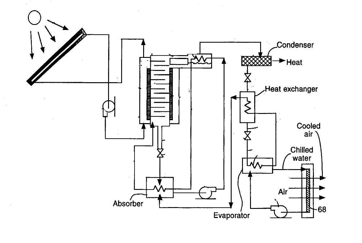
Figure : solar vapour absorption system
The heat required for the generator to
separate the ammonia from weak solution is achieve by solar radiation in our
system the solar radiation is concentration by reflector or solar concentrator.
First the concentrated heat from reflector is used to heat the water and so
that water is converted into steam that steam is use to heat solution steam
which is coming out from generator is recirculated and regenerated to required
state .
DESIGN & CALCULATION OF VAPOUR ABSORPTION REFRIGERATION SYSTEM
The operating pressures at which the system is working
needs to be determined to carry on further calculations, using an enthalpy
concentration chart. Once the pressure of the condenser (Pc) and the pressure
of the evaporator (Pe) are determined the corresponding points can be fixed on
the chart as shown in fig. 4. The various other points and condition lines for
components like absorber, generator, heat exchangers etc can be subsequently
fixed.
CONDENSER PRESSURE :
The pressure to be maintained in the condenser for
changing the phase of ammonia vapours into ammonia liquid depends on type of
condensing medium used and its temperature. In this system, water is used as a
condensing medium. Generally water is available at a temperature of 25 0C.
I.e. condensing temperature is Tc= 25 0C. For condensing ammonia
vapours at 250C, the corresponding pressure required can be noted
from the refrigeration table of ammonia (R-717). In this way, the condenser
pressure is fixed at Pc=10 bar.
3.2 EVAPORATOR PRESSURE :
The evaporator pressure can be fixed according to
the minimum temperature required to be maintain in the evaporator chamber. The
minimum temperature attained is not a designing criterion in this system. The
pressure maintained in the evaporator should be as close to the atmospheric
temperature as possible, because for maintaining the higher pressure in the
system is difficult and costly. And at below the atmospheric temperature
leakage problem is there. So that we have to taking the evaporator temperature
1 bar. The temperature related to the 1 bar in pressure enthalpy diagram is -32
0C.
3.3 ENTHLPY CONCENTRATION DIAGRAM :
The enthalpy concentration diagram for a mixture is
the most useful diagram from the practical point of view. The concentration for
nh3 is show along an x axis and enthalpy show along the y axis. On this diagram
the pressure line and temperature line is shown. The line above the graph show
the enthalpy for the vapour refrigerant and below show the liquid refrigerant
line. At the C=0 that the no ammonia present in the mixture, and for C=1 that
there is no water in the mixture.
Where, C


Figure : enthalpy concentration diagram
Now
for finding the enthalpy at different point we use the enthalpy concentration
diagram of the aqua-ammonia concentration diagram. We plot the different point
on the graph as per their property on that point.

Figure: Practical ammonia water h-c diagram
Now
the point of condenser pressure and evaporate pressure can be plotted on the
pressure enthalpy chart as points 1, 2, 3 and 4.
Point-1 represent pure NH3 saturated vapour at
condenser pressure Pc and concentration C=1.
Point-2 represent pure NH3 saturated liquid at Pc=10
bar and C=1 this point is marked in liquid region.
Point-3 represent the condition of pure NH3 (wet) but
at pressure at 1 bar and C=1.point 2 coincides with point 3 as 2-3 is
throttling process in which enthalpy remain constant.
Point-4 represents the condition of pure NH3 at pressure Pe these are
saturated vapours which absorbs
heat in evaporator and converts from wet vapour to saturated vapour. This point
is marked in vapour region. From
that we find the enthalpy of point 1, 2, 3 and 4 given below,
h1 = 1630 KJ/Kg h2-3 = 460 KJ/K h4 = 1530 KJ/Kg
Now, let as assume the refrigeration capacity of the
unit to be 1TR.
1. The refrigerating effect produced or the heat
absorbed by ammonia refrigerant in the evaporator is Qe= h4 – h3 KJ/Kg of
ammonia Say the mass flow rate of ammonia in the evaporator be Mr.
Therefore,
Mr. × (h4 – h3)
=0. 1 TR
Mr. × (h4 – h3) =
21 KJ/min
Therefore, Mr. ×
(1630 - 460) = 21
It
gives Mr. = 0.018 Kg/min
Now, the temp.
Of the water going inside the generator is more than 75 oC (about 80
0C). That is, taking the temp. In the generator Tg = 75 0C
(assuming losses) Thus the point 8 can be marked on the pressure enthalpy chart
where the constant temp line of 75 0C intersects the pressure line
of 10 bar. Point 8 represents the hot weak liquid having concentration Cw
inside the generator. Thus the corresponding concentration of the weak solution
can be directly noted down from the chart as Cw = 0.570 After fixing the point
8, the point 5 can also fixed, Point 5 represents the strong aqua coming out of
the absorber after absorbing the vapours coming out of the evaporator. The
concentration of the strong solution, say Cs can be determine by the
degasifying factor.
• Degasifying factor:
It is the amount of
NH3 vapours removed from the strong solution in the generator. Higher value of
this factor is desirable because its higher value prevents water from being
evaporated, which creates trouble, and is necessary to be removed before
entering into condenser.
So that generally for any system the strong solution
having the concentration Cs=
0.6. And the concentration for weak solution is
Cw = Cs –
degasifying factor
= 0.600 –
0.030
= 0.570
• Now
we know the pressure and concentration of point 5 so that we locate the point
5.
Point 6: This is the condition of the aqua solution
whose concentration C5 = 0.6, but the pressure is increased from Pe to Pc as it
passes through the pump. Point 6 coincides with point 5 on the C-h chart as
enthalpy does not change when the aqua pressure increase passing through the
pump.
Point 7: As the strong low temperature aqua solution
passes through heat exchanger it gains the heat and its enthalpy increases, but
its concentration Cs remains same as well as pressure remains same as
Pc. Now the point 7 can be marked on the C-h diagram as pressure at 7 and C7
are known.
• Now
join points 8 and 7 and extend till it cuts the Y axis (enthalpy) at ‘a’ as
shown in figure, then join point ‘a’ and 5 and extend till it cuts the vertical
line passing through 8. This also decides the position of point 9 and 10. Point
9: This shows the condition of weak liquid coming out of the heat exchanger
after giving heat to the strong solution. So enthalpy is reduced. Subtracting
the heat lost by the weak solution in heat exchanger, point 9 can be marked as
the concentration does not change.
Point 10: The point 10 represents the same enthalpy
as 9 but at reduced pressure Pe as it passes through the pressure reducing
valve.
• ABSORBER:
In absorber, the pure NH3 gas
enters at condition 4 and weak aqua solution enters at condition 10 and after
mixing, strong aqua comes out at condition 5. The mixing occurring inside is
underlined but aqua condition coming out is definitely known. Join the points
10 and 4 and extend the vertical line passing through point 7 till it cuts at
point 7". Now we can say that mixing taking place along the line 4- 10 and
at pressure Pe and resulting aqua is coming out at 5 after losing heat in the
absorber. Joining the points 4 and 10 and marking point 7" is not
necessary for solving the problems or designing the system components.

Figure : Condition of absorber
GENERATOR:
In generator, strong aqua is heated by supplying heat
Qg, The strong aqua enters into the generator at condition 7 and pure NH3
vapour comes out at condition 1 and weak aqua at condition 8. Now join the
points 8 and 1 and extend the vertical line through point 7 to mark the point
7" which cuts the line 1-8. Now, we can say that the separation is taking
place along the line 1-8 and at pressure pc. Joining the points 1 and 8 marking
the point 7" is not necessary for solving the problems or designing the
system components.

Figure condition of generator
CALCULATE
THE DATA FOR DESIGN :
Ø Mass
flow rate of the ammonia is 0.018 kg/min.
Ø Heat
removed in the evaporator = Cooling capacity
= Refrigeration effect
= Mr. [h4 – h3]
= 0.1 Ton =21 KJ/min
Ø Heat
removed in condenser that is the heat
carried out by circulating the water in the condenser
Qc = Mr. [h2 – h1]
= 0.018
[1630 – 460]
= 21.16
KJ/min
Heat
removed from absorber
When the NH3 vapour at point 4 and aqua at 10 are
mixed, the resulting condition of the mixture in the absorber is represented by
7” and after losing the heat in the absorber (as it is cooled), the aqua comes
out at condition 5. Therefore, the heat removed in the absorber is given by
Qa = (h7” – h5) per Kg of aqua
Extend the triangle 10-7”-5 towards right till 10-7”
cuts at 4 and 10-5 cuts at point ‘a’ on x axis.
Therefore, heat removed per kg of NH3 is given by Qa
= (h4 - ha) per kg of ammonia
Qa =
Mr. × (h4 - ha)
=
0.018 × (1550 - 70)
=
26.64 KJ/ min
Thus, Qa =
26.64 KJ/min
• Now
the resultant aqua is at condition 7”, which loses heat up to condition 5. Temp
at 7” = i.e. T7” = 70 0C (from C-h chart) Say, water gets heated to
a temp of 82 C from 25 0C
while removing heat from the absorber.
If Mw = mass
of cooling water required Then
Mw × Cp × (Ti – T0) = 26.64
Mw × 4.18 × (70 - 25) = 26.64
Mw =0.141 Kg/min
That is, the mass of cooling water required in
absorber is 0.141 kg/min.
• Heat
given in the generator Say Qg is the heat supplied in the generator and Qd is
the heat removed from water vapour then the net heat removed per kg of aqua is
given by qg – qd = (h7’ – h7) per kg of aqua as the aqua goes out in at
condition 7 and comes out at condition 8 and 1, which can be considered as a
combined condition 7’. By extending the triangle 8-7-7’ towards right till 8-7’
cuts at 1 and 8-7 cuts at a on y axis, then the heat removed per kg of NH3 is
given by
Qg – Qd = (h1 – ha) per kg of ammonia
• Now
for finding out Qd separately, extend the vertical line 7-7’ till it cuts the
auxiliary line Pc and mark point ‘b’ as shown. Then draw a horizontal line
through b which cuts Pc line in vapour region at point 11. Then join the points
7 and 11 and extend the line till it cuts y axis at 12.
Then, Qd is given by Qd = (h12 –h1) per kg of ammonia
Qd = 0.018 × (1760 - 630) Qd = 2.34
KJ/min
Now using equation Qg – Qd = (h1 - ha)
We have Qg – 2.34 = 0.018 × (1630 - 70)
So that Qg = 30.42 KJ/min
•
Thus the amount of heat required in the
generator for running this unit is
Qg = 30.42
KJ/min
Design and
Calculation Of Solar
Parabolic Reflector
BASICS FOR THE CALCULATION OF DIRECT RADIATION :
For
calculation purposes, the sun may be treated as a radiant energy source with
surface temperature that is approximately equal to that of a blackbody at 6000
K.
The sprectum of wavelength of solar radiation
stretches from 0.29 μm to about 4.75 μm, with the peak occurring at about 0.45
μm (the green portion of visible spectrum). Table 32.1 shows spectral
distribution of solar radiation with percentage distribution of total energy in
various bandwidths
|
Type of
radiation
|
Wavelength
band
(μm)
|
|
% of
total radiation
|
|
Invisible
ultraviolet (UV)
|
0.29 to
0.40
|
|
7
|
|
Visible
radiation
|
0.40 to
0.70
|
|
39
|
|
Near
Infrared
(IR)
|
0.70 to
3.50
|
|
52
|
|
Far
infrared (FIR)
|
4.2 o
4.75
|
2
|
|
Fig.no.-11: bandwidth of radiation
Total solar
irradiation:
In order to calculate the building heat gain due to
solar radiation, one has to know the amount of solar radiation incident on
various surfaces of the building. The rate at which solar radiation is striking
a surface per unit area of the surface is called as the total solar irradiation
on the surface. This is given by:
Iiθ
=IDN cosθ + Idθ + Irθ
Iiθ
= Total solar irradiation of a surface, W/m2
IDN = Direct radiation
from sun, W/m2
Idθ = Diffuse
radiation from sky, W/m2
Irθ = Short wave radiation reflected from other
surfaces,
W/m2
θ
= Angle of incidence, degrees
The angle of incidence θ depends upon:
1. Location on earth
2.Time of the day,
3.Day of the year
The above three parameters are
defined in terms of latitude, hour angle and declination, respectively.
The planet
earth makes one rotation about its axis every 24 hours and one revolution about
the sun in a period of about 365 q days. The earth’s equatorial plane is tilted
at an angle of about 23.5o with respect to its orbital plane. The
earth’s rotation is responsible for day and night, while its tilt is
responsible for change of seasons. Figure 32.3 shows the position of the earth
at the start of each season as it revolves in its orbit around the sun. As
shown in Figure, during summer solstice (June 21st) the sun’s rays
strike the northern hemisphere more directly than they do the southern
hemisphere. As a result, the northern hemisphere experiences summer while the
southern hemisphere experiences winter during this time. The reverse happens
during winter solstice (December 21st).


Figure shows
the position of a point P on the northern hemisphere of the earth, whose center
is at point O. Since the distance between earth and sun is very large, for all
practical purposes it can be considered that the sun’s rays are parallel to
each other when they reach the earth.
DESIGN OF PARABOLIC COLLECTOR :
• Design of
the parabolic collector is depend upon the following:
1. Temperature
of the water required at the heat generator.
2. Temperature
loss in the tube.
3. Heat
require in the heat generator.
4. Efficiency
of the reflector.
for more information
dibakarkarmokar@gmail.com

Very informative blog... Thanks for sharing, Hope this helps many!
ReplyDeleteThanks
Deletenice post..very informative ...thanks for sharing.
ReplyDeleteAmmonia Refrigeration plant| Ammonia Refrigeration plant supplier, Manufacturer, contractor - Manik Engineers
Thanks a lot
DeleteDesign Of Vapour Absorption Refrigeration System Working On Solar Heat Generator >>>>> Download Now
ReplyDelete>>>>> Download Full
Design Of Vapour Absorption Refrigeration System Working On Solar Heat Generator >>>>> Download LINK
>>>>> Download Now
Design Of Vapour Absorption Refrigeration System Working On Solar Heat Generator >>>>> Download Full
>>>>> Download LINK wv
Thanks for sharing
ReplyDeleteLooking for high-quality Temperature indicator suppliers ? Shakti Mechanical Works offers reliable and durable temperature indicators for industrial and refrigeration applications.
ReplyDelete